NOTE: The program was wrote using the CCS C compiler PIC C with a license PCWHD
The next program reads the 10-bit ADC of the PIC18F2550, channel 0(pin 2), and send the higher 8 bits of the result through the port B
The sampling rate is 1kHz approximately.
  1: #include <18F2550.h>			//Selecting the microcontroller
  2: #fuses HS,NOWDT,NOPROTECT,NOLVP		//Selecting set-up (high freq oscillator, no watch dog timer, et)
  3: #use delay(clock=20000000)		//We gonna use a 20MHz crystal
  4: void main()				//Main function
  5:  {    unsigned int8  value;		//Defines a variable called "value", length 8 bits
  6:    setup_adc_ports(AN0);		//Defines wich port will be used for the ADC module, ANO (pin 2)
  7:    set_tris_b(0xFF);     		//Sets the whole port B as output
  8:    setup_adc(ADC_CLOCK_DIV_32);         //Selects the TAD=1.6us (Xtal=20MHz)
  9:    set_adc_channel(0);                  //Selects the channel from were the measures will be taken
 10:    do	 	             	//Initiates a loop
 11: 	{
 12: 		delay_ms(1);		//Delay of 1ms between measures
 13: 		value = read_adc();        //Starts the ADC module which return a value and this value is saved.
 14: 		output_b(value);    	//The ADC returned value is sent to the port B
 15: 	}
 16: 	while (TRUE);			//The loop never ends
 17: }
Important issues:
The ADC module takes 11TAD to gat a 10-bit conversion. The TAD time is defined by the instruction
setup_adc(ADC_CLOCK_DIV_32);
In this case we divide the clock (20MHz) into 32 to get a time of 1.6us. This is the minimum time of adquisition for the ADC module. As the module takes 11 TAD to performs the conversion in 10-bit, then the total time of conversion is:
Total conversion time=11*TAD=11*(1.6uS)=17.6uS
If we wish a more accurate sampling rate we should take this value into account and subtract it from our delay routine. In this case, for a 1kHz sampling rate we should put a delay of:
Delay=1ms-17.6uS=982.4uS
This value without take into account the time that each instruction take to be executed by the micro.
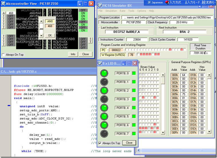
The image above shows the results of the program in a simulation made using the PIC18 simulator.
Note that for a 468 in decimal, the output in binary is 0111010100 That is the value showed by the LEDS without the two bits least significant.

The circuit in breadboard working.
References:
 I bet some day we have needed to or wanted to save a large amount of data using the common SD cards and some microcontroller.


